Design documents
Foundation plans, structural details, sections and notes can define dimensions, reinforcement, support conditions and connections.
Structural concrete can include foundation walls, footings, piers, columns and other designed elements that carry or transfer loads within the project.
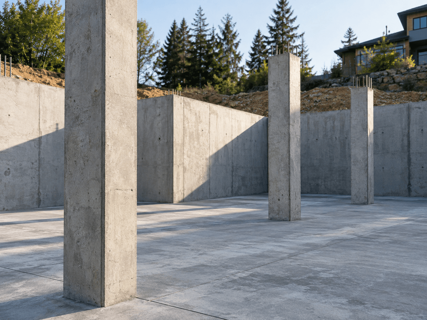
Structural concrete is not planned from a generic rule of thumb. Wall geometry, support locations, reinforcement, connections and embedded details are coordinated from the project documents.
For residential construction, structural concrete often overlaps with the foundation system and the transition to framing. A foundation wall may carry floor or roof loads, support a beam pocket, retain soil or form part of a stepped building layout.
Foundation plans, structural drawings and details establish the geometry and requirements.
Bar size, spacing, laps and placement follow the project design.
Pockets, sleeves, anchors and penetrations are coordinated before placement.
The concrete phase should account for how framing, steel, walls or other elements connect later.
The design documents, loads and interfaces around the concrete establish what needs to be coordinated before placement.
Foundation plans, structural details, sections and notes can define dimensions, reinforcement, support conditions and connections.
Footings, walls, piers and other supports work as part of the building system, so their position matters to what they carry above.
Beam pockets, anchors, sleeves, framing connections and other embedded details should be coordinated while the forms remain accessible.
Excavation, working room, access and surrounding construction influence how a designed concrete element can be formed and placed on the actual site.
Foundation wall, footing, pier, column or another designed support.
Use current drawings, dimensions, elevations and structural requirements.
Confirm what connects to, passes through or follows the concrete work.
Access, forms, placement conditions and later construction become part of one sequence.
Poured walls can support the structure above while also defining basements, crawl spaces or grade transitions. Their geometry may include steps, corners, door openings, window openings, beam pockets and other details that have to align with the building layout.
Where columns, piers or localized supports are part of the design, their position and connection details also need to be coordinated with the surrounding work.
Structural concrete often interfaces with several other parts of the project. Utility penetrations, framing connections, anchor locations, steel supports and floor elevations are easier to address while the forms and reinforcement are still accessible.
If drawings are still being developed, an early project conversation can focus on the building type, intended concrete elements and what documents are expected next.
Project Planning Guide →Tell us what you are building, where the project is located and what stage it is in. Those basics help start a useful scope conversation.